Description of the geometry
This section describes briefly the geometry, with a particular focus on the names of the physical volumes of the various sources.
Note
The renderings on this page use the public geometry (see Geometry options).
The geometry is divided in various assemblies, as described in Visualization of the geometry.
HPGe strings
The strings assembly consists of the HPGe detectors and their support
structure.
This is shown below:
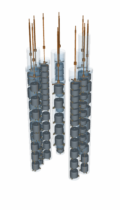
The left figure above shows the HPGe detectors, as explained in Naming conventions
these are given physical volume names of the detector name (i.e. V99000A).
The center shows the detector holder structure. This is divided into several parts:
the PEN baseplates for each detector, with physical volume names
hpge_assembly_plate_pen_{NAME}where{NAME}is the detector name.for some detectors there are also top pen rings named
hpge_assembly_top_ring_pen_{NAME},the HPGe detectors are supported by a copper support structure, all parts of this structure are made of electroformed copper and have physical volumes prefixed with
hpge_string_support_.*_copper_.parts of the holder (insulators) and clamps for the frontend electronics are made from Ultem. Their volume names are prefixed with
hpge_assembly_clamp_[signal,hv]_ultem_andhpge_assembly_insulator_ultem_.parts for the frontend electronics are made from phosphor bronze. Their volume names are prefixed with
hpge_assembly_[washer,spring]_[signal,hv]_phbr_.the copper pins connecting the receptacles to the PEN plates are prefixed with
hpge_assembly_clamp_[signal,hv]_pin_copper_.the LMFE (low-mass front-end) are implemented as a simplified box and prefixed with
hpge_assembly_lmfe_.cables are implemented in a very simplified manner; their volume names are prefixed with
hpge_cable_[signal,hv]_.nylon minishrouds surrounding each string named
minishroud_[tube,lid]_string{STRING}, and calibration tubes which have namescalibration_tube_nylon_sis{IDX}where{IDX}is the index of the SIS (see Calibration sources).
The hpge copper support structure consists of three components:
a copper rod supporting each string (shown at the top of the rendering), these have names:
hpge_string_support_hanger_copper_string{STRING}
where {STRING} is the string number,
a triangular copper support (or “tristar”) for each string named
hpge_string_support_tristar_copper_string{STRING}
copper rods for each string which have names:
hpge_string_support_rod_copper_string{STRING}_{IDX}
where {IDX} is an index of the rod (range 0–3).
Tip
To select all copper string support parts in remage you can use a wildcard
hpge_string_support_.*_copper.* to select all copper rods, tristar or string
support structures.
To select all parts made of copper, irrespective whether they are part of the
string support, use a regex like .*_copper_.*. This can be adapted for any
material.
Top plate
The top assembly consists of the top plate holding the CC4 electronics,
currently this is a single physical volume called birds_nest_plate_copper.
This is shown on the left figure of the rendering below.

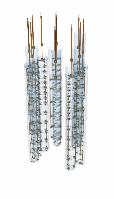
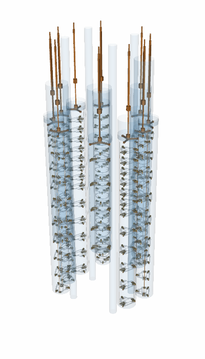
Fibers and SiPMs
The fiber shrouds for the LAr readout are shown in the right figure above.
As mentioned in Geometry options there are two modes for the optical fibers, either individual fibers or a segmented option.
In both cases the fiber volumes are divided into 4 parts:
an outer TPB coating,
two layers of cladding,
the fiber core.
The optical fiber system consists of a large number of physical volumes, to enable concise remage macros the names are first prefixed with:
fiber_inner_barrel_: for the inner barrel fibers (inner cylinder),fiber_outer_barrel_: for the outer barrel fibers.
Next the name contains an identifier of the part of the fiber either,
coating_tpb, cladding1, cladding2 or fibercore.
The rest of the names give further information on the fiber, and uses the length of the fiber, whether it is part of the lower bend for the outer barrel and the fiber index to obtain a unique physical volume name. However, only the TPB coating name contains information about the module the fibers are part of.
Tip
For more users it is expected to use wildcards to select groups of optical fibers.
The SiPMs are named after the detector name (ie S001), and there are also
physical volumes of a wrapping around the SiPMs with names
larinstr_sipm_wrap_tetratex_{NAME}[_{n}] (where {NAME} is the SiPM name).
This wrapping does not fully correspond to the wrapping used in the real
experiment, however.
The copper support structures holding the fiber shrouds is named
larinstr_support_outer_copper_.* and larinstr_support_inner_copper_.* for
the outer and inner fiber barrels. These volumes are implemented as one large
solid containing all parts.
Wavelength shifting reflector
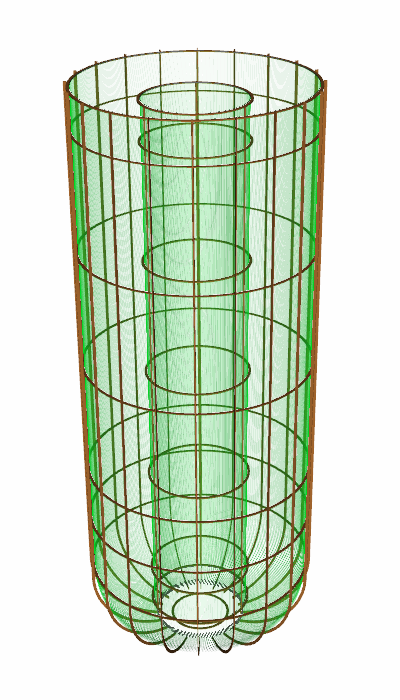
The array is emersed in liquid argon (physical volume named liquid_argon) and
surrounded by a tetratex and TPB lined copper foil for reflecting scintillation
light (WLSR).
This is shown as the outer cylinder below, which shows all the main components of the experiment. The WLSR is the shown as the outer grey component.
This consists of three physical volumes:
wlsr_copperthe copper foil,wlsr_tetratexthe tetratex coating,wlsr_tpbthe TPB coating.